Key Takeaways
• Medium choice is the settled part of the decision. Validation is the open part, and it is where links actually fail.
• A production data center is not a qualification bench. Inlet temperature, airflow, cable routing, seating quality and supply voltage all vary, and each one spends link margin.
• AI training runs on synchronous collectives, so one marginal link stalls the whole job rather than its own flow. The cable is the cheapest part of the path it can idle.
• Post-FEC error leakage is closer to real impact than pre-FEC bit error rate. Pre-FEC BER is the leading indicator, when it is visible at all.
• Advance warning of a flap depends on the retimer inside the cable, not on how new the cable is. Some links warn on the host side; some only from the far end.
• The question at 1.6T moves from “is the link up” to “how much margin does this link have, and what evidence supports that answer.”
As AI clusters move from 800G toward 1.6T, the question many infrastructure teams ask is simple: should the next build use Active Electrical Cables (AEC) or optical modules?
But that is not the first question.
Start with what a marginal link costs. AI training runs on synchronous collectives, and every rank waits for the slowest one. A single link that flaps does not just degrade its own flow — it stalls the entire job. The cable in that path costs a few hundred dollars. The graphics processing unit (GPU) node behind it costs several hundred thousand, and the cluster it belongs to costs far more. That asymmetry is the whole argument for validating the link instead of trusting the datasheet.
AECs and optics solve different problems. AECs are attractive for short, dense, power-sensitive connections inside and around the rack. They are also the more forgiving of the two to operate, because the signal never leaves the conductor. There is no free-space optical interface to keep clean, no endface contamination, and no laser to age. Optical modules are the natural answer when reach, topology flexibility and rack-to-rack scale matter more. But at 800G and 1.6T, the deeper issue is not whether copper or fiber wins. The deeper issue is whether the link has enough margin under real load, real thermals, real insertion variance and real Forward Error Correction (FEC) behavior.
Those conditions are a long way from the ones a cable is qualified in. Inlet temperature varies by rack position and by aisle. Recirculation, a blocked filter or one failed fan moves a module’s case temperature by tens of degrees. Cables get bundled, bent and routed behind the rack by whoever was on shift. Seating quality varies from one insertion to the next. Supply voltage sags when the rack draws hard, and the workload itself swings between idle and full collective traffic. A part that passes on a clean bench at room temperature has seen none of this.
In the next generation of AI data centers, link choice becomes a validation problem.
AECs Are Not Just Active Direct Attach Copper Cables
Active electrical cables sit in a useful middle ground between a passive Direct Attach Copper (DAC) cable and an optical module. They keep the operational simplicity of copper while adding active silicon to extend reach and clean up the signal. For GPU server-to-switch and short rack-level connections, that combination is powerful: lower cost than optics, lower optical-handling burden, and practical deployment in dense environments.
But the word active matters.
An AEC is not a passive piece of copper. It has retimers, firmware, thermal behavior, supply sensitivity, and state-machine behavior. At lower speeds, teams could often treat the cable as a commodity part as long as the link came up. At 800G and 1.6T, that assumption gets weaker. The active cable becomes part of the system reliability chain.
That does not make AECs inherently inferior to optical modules. It means they need to be validated like active systems, not passive accessories. That means paying attention to their firmware, retimer and state-machine behavior over time, not just whether the link came up.
Optics Win When Distance and Flexibility Dominate
Optical modules solve a different set of constraints. They give data center teams reach, routing flexibility, cleaner rack-to-rack designs, and a path toward higher aggregate bandwidth as electrical reach gets harder.
That is why optics are already central in scale-out fabrics. As cluster size grows and the physical distance between compute, switching, and storage increases, the value of optical reach becomes hard to avoid.
But optics are not free of operational risk. They bring their own failure modes: thermal sensitivity, laser aging, receive and transmit (Rx/Tx) power margin, fiber cleanliness, connector handling, and Digital Optical Monitoring (DOM) interpretation. A link can look healthy at a high level while optical power, bias current, FEC behavior or lane-level margin is already drifting. Catching that drift early means reading DOM and per-lane signals continuously and in context, not once at install.
Why 1.6T Changes the Boundary
800G already has a validation problem, and it is worth being concrete about why. At roughly 53 GBaud PAM4 the receiver works with a small eye and three decision thresholds instead of one. FEC is not a safety net at these rates — it is load-bearing during normal operation, and a healthy 800G link is already correcting errors continuously. That is why link-up carries so little information. Two links can both come up and still sit at very different distances from the point where FEC runs out of correction. Nothing in a pass/fail install test tells them apart. 1.6T makes the boundary sharper.
As per-lane speeds rise, the electrical channel gets less forgiving. 800G is mostly 8 lanes of 100G (about 53 GBaud four-level Pulse Amplitude Modulation (PAM4)), while 1.6T is mostly 8 lanes of 200G (about 106 GBaud PAM4). Doubling the Nyquist frequency roughly halves the copper reach you can hit for a given insertion-loss budget. AEC can still make sense in short, controlled paths, especially where cost and power matter. But the useful envelope becomes more selective: shorter reach, tighter thermal design, more retimer telemetry, and more careful qualification.
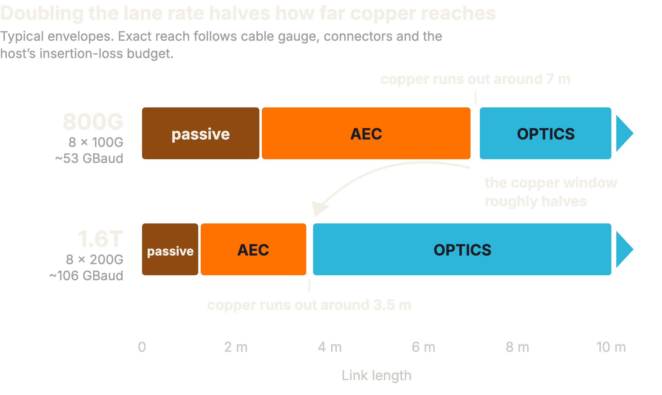
Optics, meanwhile, become more attractive as the system needs longer reach, cleaner topology, and a roadmap beyond today's rack designs.
That does not mean AEC disappears. It means AEC becomes a precision choice rather than a default assumption.
The likely future is mixed: AECs inside the short-reach, high-density parts of the cluster; optics for rack-to-rack, leaf-spine, and higher-flexibility paths. The winning design will not be all-copper or all-optical. It will be topology-driven.
Decision Table: When AEC or Optics Fits Better
Use this table as a practical lens, not a fixed rule. The right answer depends on topology, reach, thermal envelope, lane speed, serviceability, and how much telemetry the operator can collect from both ends of the link.
| Decision factor | AEC is stronger when | Optics is stronger when | Validation signals to check |
|---|---|---|---|
| Physical reach | Short, controlled paths inside or near the rack; host-to-switch connections with known cable routing. | Rack-to-rack, leaf-to-spine, or any path where routing flexibility and distance dominate. | Link margin by port, lane, and direction; far-end visibility from the switch side. |
| Cost and power | The design is cost-sensitive and the short-reach envelope is well understood. | The cost of optical modules is justified by reach, topology simplicity, or future bandwidth headroom. | Power draw, module temperature, and thermal headroom under load. |
| Thermal behavior | Airflow and cable placement are controlled, and retimer temperatures remain inside margin. | Copper thermal margin is tight or the rack design favors optical routing despite module heat. | Retimer or DSP telemetry, thermal ramp behavior, recovery path after stress. |
| Operational handling | Operators want plug-and-play copper handling with less fiber cleaning and optical inspection burden. | Operations can manage fiber cleanliness, optical power budgets, spares, and module handling discipline. | DOM, Rx/Tx power, bias current, voltage, reinsert behavior, link-down counters. |
| Failure modes | Main risks are retimer, firmware, supply, thermal, seating, or electrical margin issues. | Main risks are optical power margin, contamination, laser aging, thermal drift, or connector handling. | Pre-FEC Bit Error Rate (BER), post-FEC leakage, FEC uncorrectable. |
| 1.6T planning | Very short, controlled links where electrical reach, power, and heat can be proven. | Less controlled reach, higher topology flexibility, or paths expected to carry future speed transitions. | Margin-to-failure score, peer outliers, sustained-load testing, switch-side FEC and BER. |
How Lost Margin Becomes a Link Flap
A link flap is a link that repeatedly goes down and re-establishes, often within seconds, interrupting the traffic it carries. It is the visible end of a chain that starts well below the surface.
Every physical impairment starts the same way. Heat, a tight bend, a poor seat, a supply sag or a drifting retimer setting all show up first as a higher pre-FEC bit error rate (BER). Nothing breaks yet. FEC absorbs the errors, and from above the link looks perfectly healthy.
What has changed is the margin. Margin is the distance between the link’s operating point and the point where FEC can no longer correct what arrives. Reed-Solomon FEC does not degrade gently. It corrects up to a fixed number of symbols per codeword and fails beyond it. The transition from clean to broken is a cliff, not a slope. That is why a link can look fine right up until it does not.
Cross that cliff and uncorrectable codewords reach the layer above. That is post-FEC leakage: corrupted frames, retransmits, and a collective left waiting. Push further and the receiver loses lock entirely, link training restarts, and the port bounces. That is the flap.
So the three signals mark three different points on one chain. Pre-FEC BER says how much margin is left. Post-FEC leakage says errors are already escaping. A flap says the link ran out. Waiting for the third means learning about the problem from the workload.
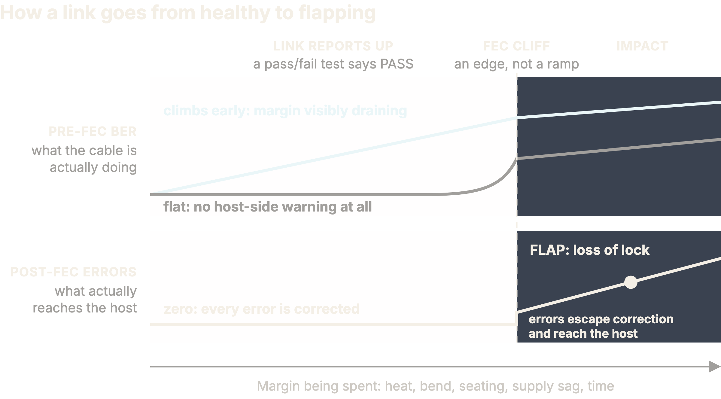
Figure 1. Margin, the FEC cliff, and the flap. Pre-FEC BER measures how much room is left; post-FEC leakage means errors are already escaping correction; the flap is what the workload finally notices. Some links warn on the host side long before the cliff, and some give no host-side warning at all.
What Our Lab Work Revealed
Our own link-flap work started with a practical question: can we detect weak AEC and optical links before they interrupt GPU workloads?
The answer is yes for some failure modes, but not by looking at a single number.
In controlled AEC testing, sustained thermal load produced degradation that mechanical bending, within the cycle count we tested, did not. One cable went through 1,020 bend cycles without measurable functional degradation: pre-FEC BER stayed near baseline, post-FEC errors stayed at zero, and no flap occurred during collection. The signal that looked suspicious at first was later explained by Serializer/Deserializer (SerDes) training and re-insertion variance, not permanent cable damage.
Thermal stress told a different story. Under sustained load and elevated temperature, pre-FEC BER increased, links flapped, and recovery behavior exposed asymmetric retimer behavior between the two ends. Figure 2 shows the split. Retimer A tracked temperature, and on the host side its pre-FEC BER climbed well before the flap. Retimer B held its error floor across the whole range and gave no obvious host-side precursor at all. The two cables differed in retimer vendor, not simply in vintage. Precursor visibility is a property of the retimer and its firmware, and it is not something a newer cable gives you automatically.
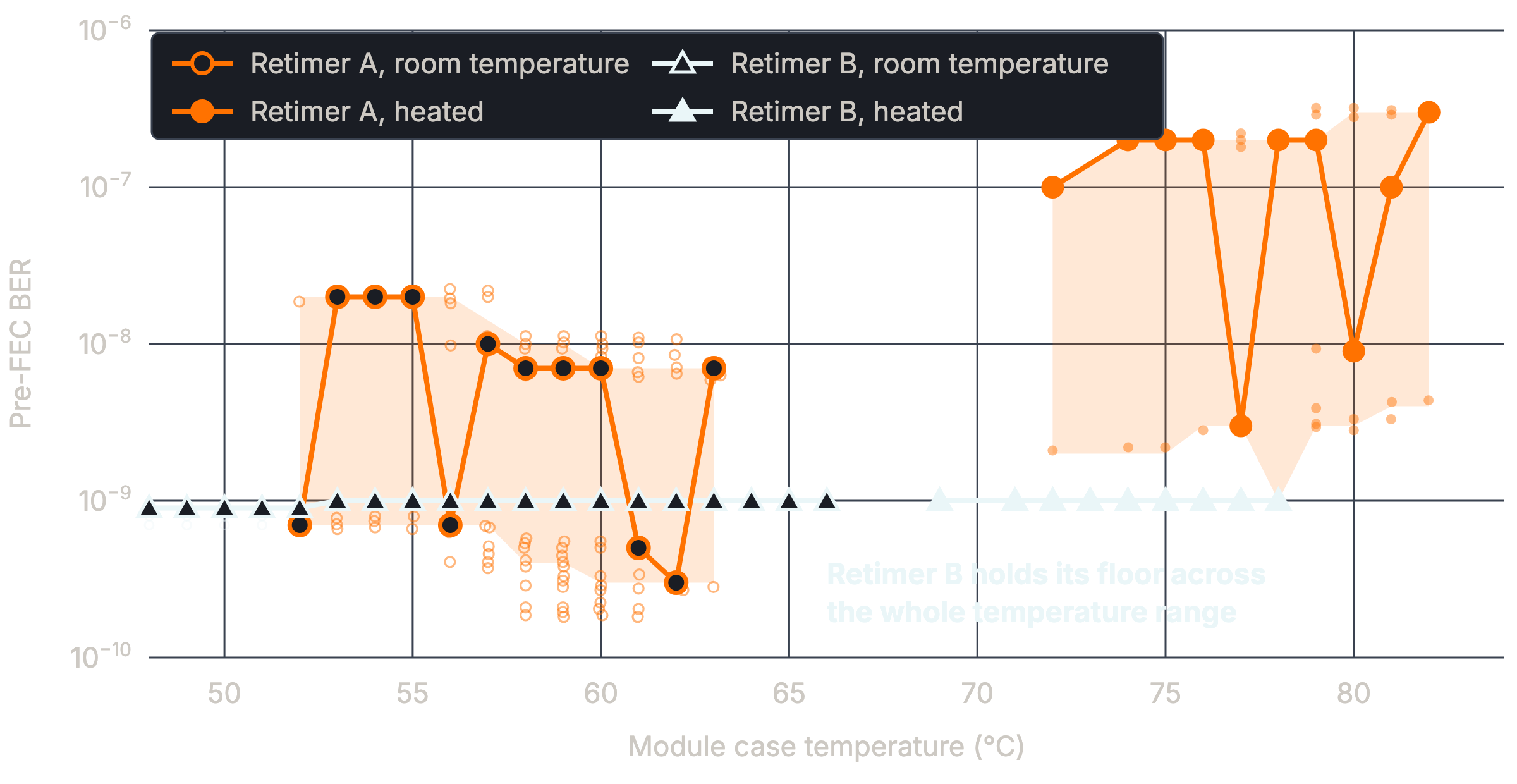
Figure 2. Pre-FEC BER against module case temperature for two 3 m 800G AECs under sustained load. The two cables differ in retimer vendor. Retimer A tracks temperature and climbs by more than an order of magnitude once the module runs hot; Retimer B sits on its floor across the whole range. Open markers are runs at room ambient, filled markers runs in a thermal chamber; shaded bands are the interquartile spread per 1 °C bin.
That last point matters. Some failures are visible before they happen. Some are not visible from the host side alone. A validation tool that only looks at link-up state, or only looks from one end, will miss important parts of the story.
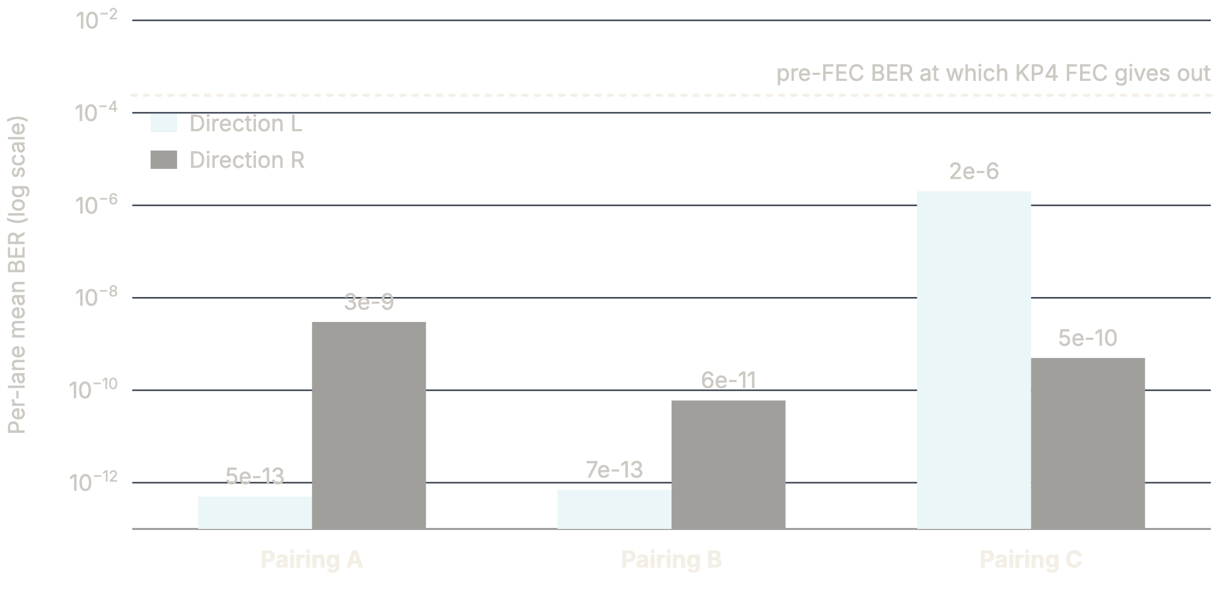
Figure 3. The same link, measured in each direction, across three cable and port pairings. Per-lane mean pre-FEC BER differs by three to four orders of magnitude between the two directions, and which direction is worse changes with the pairing. Reading from one end alone would have called Pairing A and Pairing B pristine. The dotted line marks the pre-FEC BER at which KP4 FEC gives out.
The most useful operational lesson was this: post-FEC error leakage is closer to real impact than pre-FEC BER alone. Pre-FEC BER helps describe physical margin, but post-FEC leakage tells you whether errors are escaping correction and reaching the system above. For production validation, that is the line operators care about. Pre-FEC BER and its trend are the leading indicator when they are visible: they often move first, which makes them a useful early warning. As Retimer B showed, though, that precursor sometimes appears only on the far end. Margin has to be read from both sides of the link.
Link Health Is a System Property
A GPU cluster link is not just a cable or a module. It is a path across host network interface card (NIC), rack, cable or optical module, switch port, retimer or digital signal processor (DSP), airflow, firmware, and traffic pattern.
That is why old validation habits are not enough.
A static pass/fail test can tell you that a link came up. It cannot tell you how close that link is to the edge. It cannot tell you whether a lane is consuming more FEC margin than its peers. It cannot tell you whether the far end sees degradation that the host cannot see. It cannot distinguish a weak cable from a dirty optical path, a bad seating event, a switch-port issue, or a thermal problem without more context.
At 800G and 1.6T, validation needs to move from is the link up to how much margin does this link have, and what evidence supports that answer.
What the Next Data Center Build Will Likely Do
For the current wave of AI data center builds, many teams are still optimizing around availability of parts, deployment speed, and known-good topologies. That is understandable. But the next wave will have more data from real 800G deployments and a clearer view of 1.6T tradeoffs.
Our expectation over the next 3-5 years is that AECs will remain important for short-reach, rack-level connectivity where their cost, power and deployment advantages are strong.
Optical modules will take more of the topology where reach, routing flexibility, and future speed headroom matter.
1.6T will narrow the comfort zone for electrical links, even if it does not eliminate them.
The trend reads as a clean progression: at 800G the electrical channel still has real headroom; at 1.6T that headroom narrows sharply. Linear-drive optics — Linear Pluggable Optics (LPO) — sit in the middle of this shift. Dropping the module’s DSP saves power, but it also moves more of the reliability burden onto validation, because you lose the retimer’s signal cleanup. 3.2T-class designs will push more of the discussion toward optics, and specifically toward co-packaged and near-package optics, much of it built on silicon photonics.
But the operational winner will not be the team that picks one medium everywhere. It will be the team that validates each link class against the failure modes that matter.
The Takeaway
AECs and optical modules will both have a place, and both will fail in their own ways. Both need better telemetry, better qualification, and better production monitoring than traditional rack validation provides.
That is where validation software becomes part of the infrastructure strategy: it understands the media type, collects the right signals from both host and switch, interprets FEC and BER in context, watches thermal behavior over time, and reports margin instead of pass or fail.
So at 1.6T the real question is not which cable connects the GPU cluster, but whether you can show that link has the margin to stay healthy when the cluster starts doing real work.
References
1. IEEE Std 802.3df-2024, media access control parameters, physical layers and management parameters for 400 Gb/s, 800 Gb/s and 1.6 Tb/s operation.
2. IEEE P802.3dj, task force developing 200 Gb/s per lane electrical and optical signaling for 800 Gb/s and 1.6 Tb/s Ethernet.
3. OIF Common Electrical I/O (CEI) 224G framework, 200 Gb/s per lane electrical interfaces.
4. OIF Common Management Interface Specification (CMIS), module management and per-lane diagnostic reporting.
5. IEEE Std 802.3, Clauses 91 and 119, Reed-Solomon forward error correction for high-speed Ethernet, RS(528,514) and RS(544,514).
About the Authors
Xinyu Z. is a Data Scientist at XPerf, focused on performance modeling for heterogeneous GPU clusters, workload-aware scheduling, and statistical baselines for comparing telemetry across vendor platforms. Her work helps translate complex infrastructure data into measurable performance insights that can improve how AI workloads are deployed and optimized.
Dr. Rakesh Sambaraju is President and CEO of Infraeo, a provider of high-speed copper and optical interconnects engineered for AI data centers. He brings more than 20 years across optical communications and high-speed interconnects, spanning research, application engineering, and commercialization, with prior roles at Sterlite Technologies, Nexans, and Corning. At Infraeo, he leads the company’s work on 1.6T interconnects and AI inferencing at the edge. He holds a Ph.D. in Optical Communications (summa cum laude) from the Universitat Politècnica de València.
Comments
No comments yet. Be the first to share your thoughts.